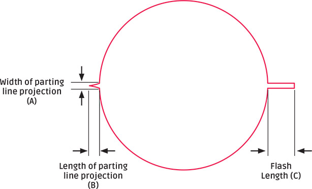
Parting line projection is a continuous ridge of material on the parting line along the ID or the OD of the ring, often caused by mold wear creating enlarged radii from the mold cavity to the flat plane of the tool. Excessive flash is a thin, film-like layer of material extending from the parting line projection.
| Specification | Max Allowable Partine Line Projection Width (A) (inches)** |
Max Allowable Partine Line Projection Length (B) (inches)** |
Max Allowable Flash Length (C) (inches)** |
|---|---|---|---|
| AS708* | .003 | .003 | 0 (all flash must be removed) |
| ISO 3601-3 CS | .0039 | .0028 | 0 (all flash must be removed) |
| AS871 | .005 | .003 | 0 (all flash must be removed) |
| ISO 3601-3 S, DIN 3771 S |
.0039 | .0039 | .0020 |
| ISO 3601-3 N, DIN 3771 N |
.0039 | .0039 | .0028 |
| MIL-STD-413C | .003 | Combined height of projection and flash must remain < .003 | |
| RMA OR-1 A | .003 | Combined height of projection and flash must remain < .003 | |
| RMA OR-1 B | .003 | Combined height of projection and flash must remain < .003 | |
**The data above shows maximum allowable width, height and flash length of defect assuming an o-ring cross sectional diameter is between 0 and .1 inches.