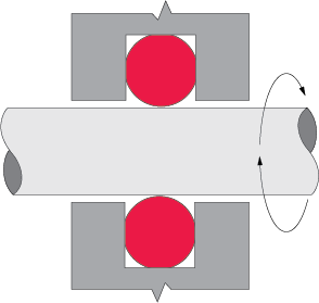
As shown in Illustration 4.7, o-rings may be used as seals for rotating shafts, with the turning shaft protruding through the I.D. of the o-ring.
The most important factors to consider in designing rotary seal glands are application temperature limits, frictional heat buildup, o-ring stretch, squeeze and shaft and glandular machining.
Illustrations
-
Application Temperature Limits
Rotary shaft seals are not recommended for applications with operating temperatures lower than -40°F, or higher than +250°F. The closer the application is to room temperature, the longer the o-ring can be expected to effectively seal.
-
Frictional Heat Buildup
As the generation of frictional heat is inevitable with rotary seal applications, it is suggested that o-rings be composed of compounds featuring maximum heat resistance and minimum friction generating properties. Internally lubricated compounds are typically used for rotary applications.
-
Stretch
In this application, I.D. stretch must be eliminated by using shaft diameters no larger than the free state no larger than the free state (relaxed) I.D. of the o-ring. Shaft seals for rotary or oscillating applications should be designed with no stretch over the shaft. When an elastomer is stressed in tension and the temperature is increased, it contracts instead of expands which increases the heat and additional contracting until seal failure. This contraction of an elastomer due to increased temperature is known as Joule effect.
-
Squeeze
In most rotational shaft applications, o-ring squeeze should be kept to as little as 0.002" by using an o-ring with an O.D. of about 5% larger than the accompanying gland. Once installed, peripheral compression puts the o-ring's I.D. in light contact with the turning shaft. This design minimizes frictional heat buildup and prolongs seal life.
Rotary Seal Gland Dimensions
Recommended dimensions for rotary seal glands. For the complete table, see Rotary O-Ring Seal Gland Dimensions Under 900 PSI.
| AS568 Number | O-Ring Dimensions | B Shaft Diameter |
A Groove Diameter |
D Rod Bore Diameter |
G Groove Width |
||
|---|---|---|---|---|---|---|---|
| I.D. ±Tol. | W ±Tol. | O.D. (ref) | |||||
| Tolerance | +.000 -.001 |
+.003 -.000 |
+.003 -.000 |
+.004 -.000 |
|||
| -004 | .070 ± .005 | .070 ± .003 | .210 | .072 | .202 | .084 | .075 |
| -005 | .101 ± .005 | .070 ± .003 | .241 | .103 | .233 | .115 | .075 |
| -006 | .114 ± .005 | .070 ± .003 | .254 | .116 | .246 | .128 | .075 |
| -007 | .145 ± .005 | .070 ± .003 | .285 | .147 | .277 | .159 | .075 |
| -008 | .176 ± .005 | .070 ± .003 | .316 | .178 | .308 | .190 | .075 |