In our first article, “A Comparison of Actuation Forces: Material and Hardness,” we used the same o-ring size and groove size to discover the effect of different o-ring materials on actuation forces. This article evaluates how the groove size plays an essential role in influencing these forces.
Customers often come to us complaining that an o-ring is causing high insertion forces during assembly, or that they are not able to assemble the mating components at all. Along with the high insertion forces, customers may report damage to the o-ring in the form of shear or peripheral abrasion. As a result, a common request is if we can hold +/- 0.001” tolerance on the o-ring cross-section. This tolerance is almost impossible based on batch-to-batch variations. This is why having the proper groove design is so important. Going to 100% inspection to meet tighter tolerances to compensate for a bad design increases part cost to the point that it may no longer be economical for the application.
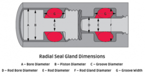
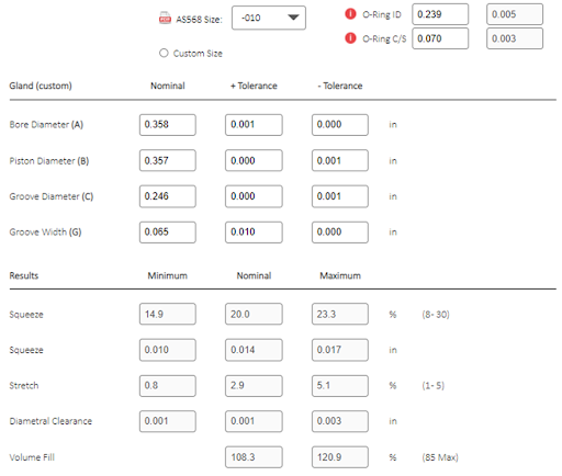
On our website, the Gland Calculator is a tool for Design Engineers for evaluating groove design. It is a useful tool for evaluating the squeeze, stretch, and volume fill of the o-ring in the specific gland design. When the calculations are complete, we typically find that the design has too high of a volume fill. This means too much o-ring volume is being forced into too small a gland void. It is important to note that rubber acts as an incompressible fluid. When a force to squeeze the rubber is applied, the material does not compress, but rather displaces the volume into the available void of the gland. As the gland fill moves toward 100%, the force to squeeze the o-ring increases exponentially. A good rule of thumb is to keep the volume fill below 85% while having 10% to 40% squeeze for static and 10% to 30% for dynamic applications. For standard AS568 o-rings there are predefined gland dimensions which are found in Aerospace Recommended Practice (ARP)-1233 and provided in our Seal Design Guide (SDG) and the online Gland Calculator.
In this test, we are measuring the force to actuate the piston using different Gland Width configurations, thus changing the volume fill. We measure both static and dynamic forces.
Static force: the maximum force required where the o-ring can no longer withstand the external push.
Dynamic force: the average force the o-ring exerts back while being pushed.

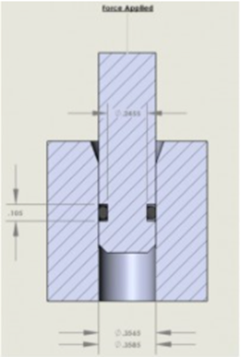
Using the o-ring Gland Calculator, we input the following Groove Width sizes: 0.1050, 0.0852, 0.0757, and 0.0649 inches – then record the calculated Volume Fill results. Below are the example calculations for the Groove Width of 0.064, resulting in a Volume Fill greater than 100%.
The results from the o-ring Gland Calculator are as follows:
| Groove Width (inch) | Nominal Volume Fill (%) | Maximum Volume Fill (%) | Minimum Squeeze (inch) | Maximum Squeeze (inch) |
| 0.1050 | 67.0 | 74.7 | 0.010 | 0.017 |
| 0.0852 | 82.5 | 92.1 | 0.010 | 0.017 |
| 0.0757 | 92.9 | 103.6 | 0.010 | 0.017 |
| 0.0649 | 108.3 | 120.9 | 0.010 | 0.017 |
The results of the actuation testing are as follows:
| Nitrile, 70A | Fluorocarbon, 75A | |||
| Grove Width (inch) | Static Force (lbf) | Dynamic Force (lbf) | Static Force (lbf) | Dynamic Force (lbf) |
| 0.1050 | 3.545 | 1.538 | 7.072 | 3.157 |
| 0.0852 | 3.401 | 1.279 | 7.189 | 2.673 |
| 0.0757 | 3.398 | 1.531 | 6.830 | 3.706 |
| 0.0649 | 82.621 | 9.419 | 122.915 | 37.082 |
Nitrile (Buna-N): Groove Width vs. Force
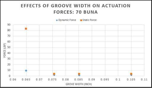
AS568-010 size was selected using a standard Nitrile rubber compound with a hardness of 70A. The graph shows dynamic and static forces for each groove width.
Fluorocarbon (Viton®): Groove Width vs. Force
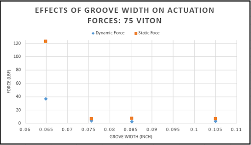
AS568-010 size was selected using a standard Fluorocarbon rubber compound with a hardness of 75A. The graph shows dynamic and static forces for each groove width.
Based on the results, it can be concluded that when the Volume Fill exceeds 100%, the actuation forces increase exponentially.
Actuation force with regard to materials and hardness compression testing was completed in another Hot Topic: A Comparison of Actuation Forces. These tools are available to better benefit our customers. Contact one of our engineers today to learn more about how we can help with your next project.