One of the keys to creating a functional o-ring seal involves evaluation of o-ring volume and groove volume. Experimental analysis and experience have shown that elastomer o-rings must always be smaller than the grooves they fit in. If the o-ring volume approaches the groove volume, forces increase and shearing failures become apparent. To minimize forces, the o-ring should never be larger than 85% of the groove.
Several o-ring groove recommendations are available. Most reference SAE Aerospace Recommended Practice (ARP) 1231 – Gland design, Elastomeric o-ring seals, general considerations. This specification and others referenced generally recommend a ratio of o-ring volume to groove volume of approximately 65%. This means that the o-ring only fills 65% of the groove. While 65% gland fill might be overly conservative, it does mean that the groove will be larger than the o-ring in nearly all situations.
Figure 1 shows an AS568C-010 o-ring compressed in a groove designed to SAE ARP-1233; Gland Design for Dynamic radial seals. Note that the o-ring is much smaller than the groove. Figure 2 shows a groove that is narrower than the recommended width. The o-ring in this configuration fills approximately 90% of the groove. Experimental data shows that as the o-ring fills more of the groove and begins to touch the groove on all 4 sides, the force needed to actuate the seal increases. When the o-ring volume approaches the groove volume, the o-ring begins to shear when inserted, as shown in Figure 4. An experiment was conducted to evaluate this phenomenon using a piston-and-bore fixture, shown in figure 5. This fixture was placed in a universal testing machine to measure insertion and actuation forces associated with various groove fill percentages.
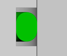
Figure 1 : ARP-1233 Recommended Design O-ring filling approximately 65% of groove
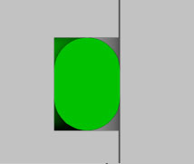
Figure 2 : Narrower width groove with o-ring touching o-ring filling approximately 85% of groove
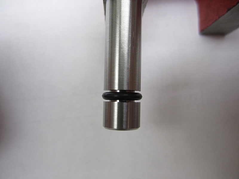
Figure 3: ARP-1233 o-ring and groove
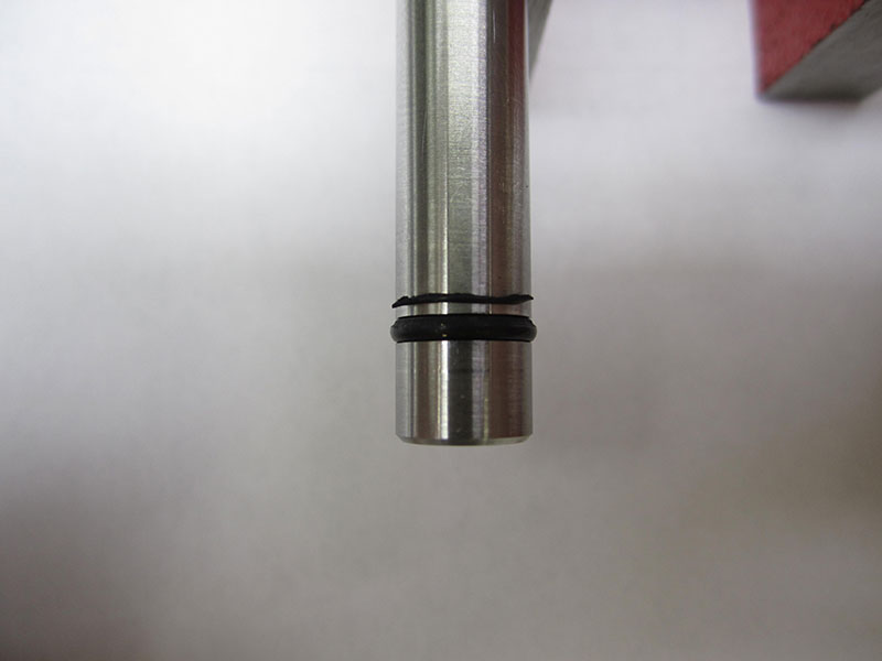
Figure 4: Sheared o-ring
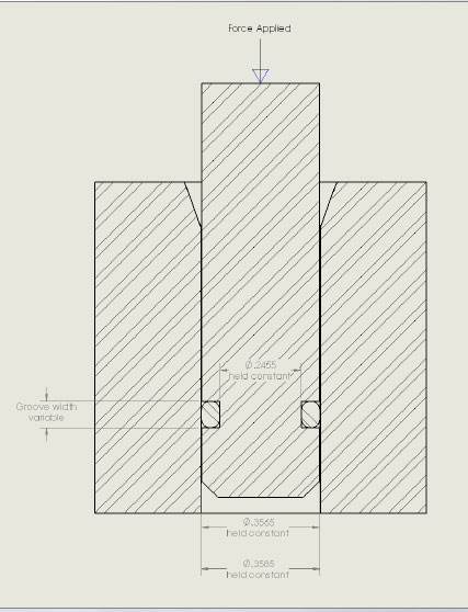
Figure 5: O-ring force testing fixture
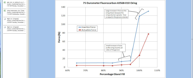
Figure 6: O-ring forces vs % gland fill