A dynamic seal application is best described as one where there is motion between a hardware component and thesealing element. This motion can be reciprocating, rotary, or oscillating. In the case of a valve stem seal, it may also be a combination of more than one type.
Let’s consider these applications and walk through some of the most common single component elastomeric seals.
Reciprocating Seals
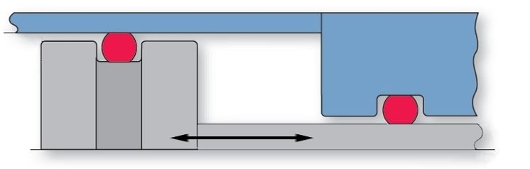
Reciprocating seals are used in applications involving a moving piston and/or a rod. These seals constitute the predominant dynamic application for O-rings. Here is a link for the Dynamic Radial Seal Gland design table for standard AS-568 O-rings.
For optimum performance of reciprocating seals, you have to take a few factors into consideration.
Compound Selection for Thermal Cycling
Thermal cycling from high (100°F and above) to low (-40°F and below) temperatures may cause O-rings to take a compression set at elevated temperatures and fail to rebound enough at low temperatures to provide a leak-proof seal. Such O-ring leaks are especially prone to occur in low pressure, reciprocating applications. Therefore, when extreme operating thermal cycles are anticipated, it is recommended that you specify a seal compound that exceeds, rather than merely meets, desired temperature range, compression set, and resilience needs.
Pressure shocks
With sudden stopping and holding of high loads, hydraulic components can create system pressures in excess of seal extrusion resistance capabilities. To prevent extrusion and eventual O-ring failure, pressure shocks should be anticipated and effectively dealt with in both seal selection and system design. As required, accumulators or pressure relief valves may have to be built into the hydraulic system.
The use of back-up rings or increasing the seal durometer may also be necessary to prevent O-ring extrusion. Follow this link for more information on the Effects of Pressure.
Squeeze
Refer to O-Ring Gland Design For Dynamic Seals for general gland guidelines. Lower squeeze than that shown in Table A will reduce friction, but at a cost of possible leakage in low pressure conditions. Greater squeeze than that shown will increase friction and ability to seal, but at a cost of difficult assembly, faster seal wear and the increased potential for spiral failure.
Stretch
When the I.D. of an O-ring is stretched, the O-ring’s cross section is reduced. In such instances, be sure to consider that the O-ring’s reduced cross section maintains the correct percentage of seal squeeze. The percentage of stretch should not exceed 5% in most applications.

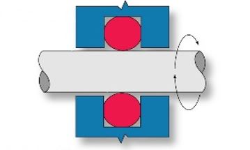
Rotary Seals
A rotary seal application is that of a turning shaft protruding through the I.D. of a seal component. The most important factors to consider in rotary seal designs are application temperatures, frictional heat buildup, seal stretch, squeeze, and shaft and glandular machining. Check out our Rotary Seal Gland design tables for standard AS-568 O-rings.
Application Temperatures
Rotary shaft seals are not recommended for applications with operating temperatures lower than -40°F, or higher than +250°F. The closer the application is to room temperature, the longer the O-ring can be expected to effectively seal.
Frictional Heat Buildup
As the generation of frictional heat is inevitable with rotary seal applications, it is suggested that the seal be composed of compounds featuring maximum heat resistance and minimum friction generating properties. Internally lubricated compounds are typically used for rotary applications.
Stretch
In rotary seal applications, I.D. stretch must be eliminated by designing shaft diameters no larger than the free state (relaxed) I.D. of the seal. Shaft seals for rotary or oscillating applications should be designed with no stretch over the shaft. When an elastomer is stressed in tension and the temperature is increased, it contracts instead of expands which increases the heat and additional contracting until seal failure. This contraction of an elastomer due to increased temperature is known as the Gough-Joule effect.
Squeeze
In most rotary shaft applications, O-ring squeeze should be kept to as little as 0.002″ by using an O-ring with an O.D. of about 5% larger than the accompanying gland. Once installed, peripheral compression puts the O-ring’s I.D. in light contact with the turning shaft. This design minimizes frictional heat buildup and prolongs seal life.
Gland Design for Dynamic Seals (O-Ring and X-Ring)
Machining
To minimize premature wear and seal failure, the hardware surfaces which contact the seal during installation and system operation must be properly prepared. Preparation consists of appropriate selection of materials, as well as machining for optimum surface finish.
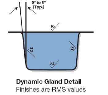
To prevent seal extrusion or nibbling, rectangular, straight-sided, glandular grooves are best. For pressures up to 1,500 psi, 5° sloping sides are acceptable and easier to machine or mold. Break all sharp corners by at least 0.005″ to avoid unnecessary cutting or nicking of the seal during assembly and operation.
Surface Finish (Reciprocating seals)
A highly polished surface is not desirable because it will not retain the needed lubrication. The most desirable metal surface roughness for dynamic seal applications is from 10 to 20 micro-inches. A shot-peened or electro-polished surface is ideal, because it provides small pockets in the metal for entrapment of lubricants. The best surfaces are honed, burnished or hard chrome plated. Softer metallic surfaces, such as aluminum or brass, should generally not be used for dynamic applications unless they have a hard plated surface.
Rotary Seals
Shaft composition should be of a relatively hard metal and be within 0.0005″ TIR. Additionally, it is recommended that shaft surfaces be finished to 16 RMS (for smooth, non-abrasive running), with gland surfaces finished to a rougher 32 RMS (to discourage seal movement within the gland).
Dynamic Seals
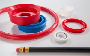
O-Ring
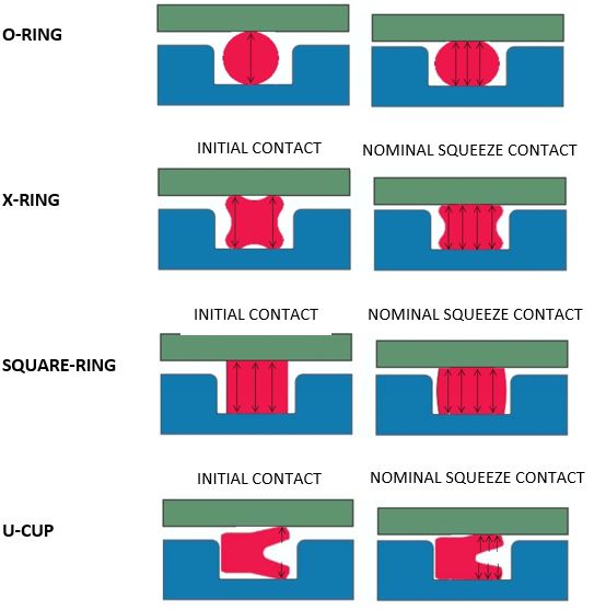
An O-Ring is the most widely used type of seal. The round cross-section is economical to produce and provides a bi-directional seal that is easy to install. When applied correctly the O-Ring will function well in most dynamic applications. The round cross-section provides a point load – initial squeeze produces minimal surface contact area.
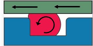
Because an O-ring has a round cross-section, it will tend to roll or spiral in long stroke reciprocating applications. This tends to happen in dry applications where the frictional forces between the seal and moving component exceed those in contact with the gland walls.
X-Ring
n X-ring can also be referred to as a quad-ring. The cross-section is similar to that of a four leaf clover. Like an O-ring, the X-ring is a compression seal. When initial squeeze is applied there are two solid bands of the cross-section in compression. The X-ring provides a more stable cross-section than the O-ring, therefore it is recommended for those long stroke applications, or where a wider foot print seal is a benefit.
Square-Ring
A square-ring may also be referred to as a lathe-cut ring, which has more to do with the process of manufacturing the ring. Just like the O-ring and X-ring, the square-ring is a compression seal.
However, initial squeeze produces a compression band across the full contact surface. The large contact area, and resulting friction, does not make this type of seal a good choice for dynamic applications.
U-Cup
There are many variations of U-cups. This type of seal is also referred to as a lipped seal. The U-cup is a unidirectional seal – it will only seal in one direction. Unlike the previous rings mentioned, the U-cup is not a compression seal. When installed the lips are deflected, and there is typically no solid compression band. The system pressure energizes the seal lips to create the primary seal.
The best U-cup designs have a cross-section that is more rectangular than square. This provides better stability in long stroke and potentially dry reciprocating applications. Because the U-cup is pressure energized, the seal can be made with a harder, high modulus seal material that has excellent abrasion and wear resistance.
Comparison of Contact Area and Seal Geometry
Note, dynamic seals do leak. It is important to know how critical leakage is to the application, and make design adjustments accordingly. Friction, wear, ability to seal, extrusion, and stability are fundamental characteristics to take into account when evaluating a dynamic sealing application.
Fundamentals of Dynamic Sealing
Friction
To Lower Friction, keep the following in mind:
- Reduce squeeze (unit load)
- Reduce surface finish (16 RMS is ideal)
- Increase lubrication
- Reduce surface contact area
- Reduce pressure
- Increase speed of motion
Wear
Seal Life is influenced by the following:
- Material selection
- Surface finish of hardware
- Presence of lubrication
Sealability
To improve sealability, try the following:
- Increase squeeze (unit load)
- Increase surface contact area
- Increase pressure (1,500 psi. max. for seals presented in this article)
- Select a Compression seal geometry over a U-cup design
Extrusion
To lower seal extrusion, try the following:
- Reduce the extrusion gap
- Increase durometer
- Reduce pressure
Stability
In order to improve stability:
- Select seal geometry with non-round cross-section
- Stretch: Increase ID Stretch for Piston Applications
- Reduce ID Stretch for Rod Applications
Have questions or comments on this topic? We’d love to talk dynamic seals with you. Contact our engineers or connect with us on Twitter.