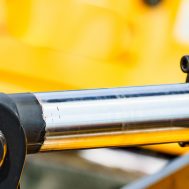
Dynamic seal application can be described as when motion is present between a sealing element and a hardware component. These seals vary from static seals, which are applied between any parts that do not slide, shift, or rotate. As a reminder, dynamic seals create a shield-like barrier to keep out gasses, liquids, contaminants, as well as hold pressure.
Though dynamic seals are used in scenarios involving reciprocating, oscillating, or rotating motion, we’ll be going over the specific uses and functions of dynamic seals in general and those with reciprocating natures.
What Goes into Dynamic Seal Design
Since dynamic seals are frequently in motion, they must be made of materials that offer strength and high abrasion resistance. They can be made of self-lubricating materials or low-friction compounds such as FKM rubbers. The constant motion of dynamic seals may risk premature failure and necessitate maintenance. One way to prevent premature wear is to have a gland design that, during motion, does not scrape the o-ring.
About Reciprocating Seals
You can find reciprocating seals in applications using a rod and a moving piston. Out of the other two types of seals (oscillating and rotating), reciprocating seals are the main dynamic application for o-rings. As such, they are used in the robotics field for sealing linear actuators and the automotive industry with brake cylinders and shock absorbers. Since these seals are used in many fields, it is important to consider certain factors to ensure a high level of performance.
Compound Selection for Thermal Cycling
Due to thermal cycling from high (100°F/37°C and above) to low (-65°F/53°C and below) temperatures, o-rings can take a compression set at elevated temperatures and fail to bounce back enough at low temperatures to provide a leak-proof seal. These o-ring leaks are at a higher risk of happening in low-pressure, reciprocating applications. If you anticipate extreme operating thermal cycles, we recommend selecting a seal compound that exceeds (rather than meets) your desired temperature range, compression set, and resilience needs.
Pressure Shocks
Hydraulic components, with their abrupt stopping and holding of heavy loads, can cause system pressures greatly exceeding seal extrusion resistance capabilities. To prevent extrusion and eventual o-ring failure, you should anticipate and effectively deal with pressure shocks in both system design and seal selection. If needed, pressure relief valves or mechanical brakes may need to be built into the hydraulic system.
Squeeze
Our “O-Ring Gland Design for Dynamic Seals” sheet offers guidelines (see Table A) for recommended squeeze values for o-rings used in reciprocating applications. Squeeze lower than shown in Table A will result in a reduction of friction, but at the tradeoff of potential leakage in lower-pressure situations. A greater squeeze than what is shown in Table A will increase friction and sealing ability, but lead to assembly that is more challenging, faster seal wear, and an increased spiral failure probability.
Stretch
When an o-ring’s inner diameter is stretched, this reduces the o-ring’s cross-sectional area. With this in mind, consider the o-ring’s reduced cross-section maintains the correct percentage of seal squeeze. In most applications, the stretch percentage should not surpass 5%.
Looking for More Information?
Be sure to contact an engineer today.
