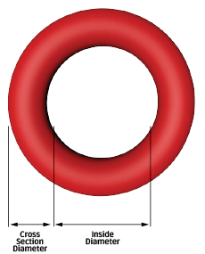
Inside Diameter
To provide an effective seal, the o-ring's inside diameter (I.D.) must be smaller than the piston groove diameter, so that the o-ring is slightly stretched, fitting snugly in the groove. This stretch should be between 1%-5% with 2% as the ideal in most piston applications. A stretch greater than 5% is not recommended. The resulting stress on the o-ring will cause accelerated aging and cross section reduction.
Exception to this rule is a floating seal. These are o-rings that are allowed to sit in grooves freely or “float.” These are typically used in pneumatic piston applications, where some leakage can be tolerated for the benefit of lower friction.
Calculate the o-ring I.D. according to the following formula:

Cross Section
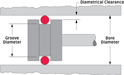
When calculating the cross section (C.S.) of an o-ring, you need to consider the size of the gland to be filled as well as the amount of squeeze needed to create a good seal. Virtually every gland has a slight gap between the two mating surfaces, termed “diametrical clearance.” Therefore, it is important for the o-ring cross-section to be greater than the gland depth. The resulting o-ring squeeze prevents leakage by blocking the diametrical gap.
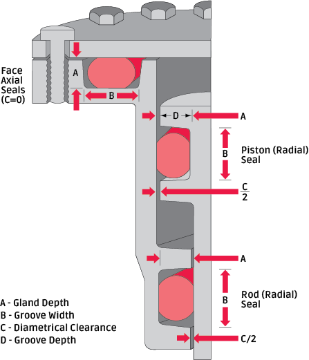
Illustration 3.1 demonstrates that in “static” face seals or “dynamic” piston and rod seals, the o-ring is being squeezed slightly within the gland. Squeeze may occur in one of two possible ways. If the squeeze occurs on the top and bottom surfaces of the o-ring, as in face seals, it is referred to as AXIAL squeeze. If the squeeze is on the inner and outer surfaces of the o-ring, as in piston or rod seals, it is referred to as RADIAL squeeze.
To obtain the correct amount of squeeze for optimum o-ring sealing, careful consideration must be given to the size of the o-ring in relation to the size of the glandular space into which the o-ring is being installed. The actual calculation for the cross section needed in an o-ring varies depending on whether it will be used in a dynamic or static application. In a dynamic situation, lower squeeze is recommended to reduce friction.
Dynamic (Moving) Radial Seal
Cross Section Calculation
Referring to Illustration 3.2 for term definition, and Illustration 3.3 for sample dimensions, calculating the correct o-ring cross section for a specific gland depth is illustrated to the right. In the case of the dynamic piston seal shown, the cross section is calculated as follows:
Calculation of Maximum O-Ring Cross Section
- Enter the bore diameter
- Subtract the bore tolerance from the bore diameter
- Enter the groove diameter
- Add the groove tolerance to the groove diameter
- Subtract line 4 from line 2
- Divide line 5 by 2
- Enter the maximum % compression
- Divide line 7 by 100
- Subtract line 8 from the number 1
- Divide line 6 by line 9
- Enter o-ring C.S. tolerance
- Subtract line 11 from line 10 for the answer

Calculation of Minimum O-Ring Cross Section
- Enter the bore diameter
- Add the bore tolerance to the bore diameter
- Enter the groove diameter
- Subtract the groove tolerance from the groove diameter
- Subtract line 4 from line 2
- Divide line 5 by 2
- Enter the minimum % compression
- Divide line 7 by 100
- Subtract line 8 from the number 1
- Divide line 6 by line 9
- Enter o-ring CS tolerance
- Add line 11 to line 10 for the answer

Static (Non-moving) Axial Seal Calculation
To calculate the cross section of an axial seal, determine the gland depth and then multiply by the maximum and minimum squeeze requirements, noting to add 1.00 to the recommended squeeze. For example, a recommended squeeze of 30% would translate to a multiplied factor of 1.3.
The o-ring I.D. is determined by the presence of pressure, whether from the I.D. or the O.D. If pressure forces the o-ring towards the inside, as shown in Illustration 4.2, then the o-ring should be designed with the I.D. close to the groove I.D. However, if pressure forces the seal to the outside, as shown in Illustration 4.1, then the seal should incorporate some inference on the O.D.
Illustrations
- Illustration 3.1, Common Applications
- Illustration 3.2, Radial Seals
- Illustration 3.3, O-Ring Profiles