
As technology advances and the demand for smaller devices grows, seals are becoming increasingly vital in various applications. MicrOring seals, developed by Apple Rubber, cater to this demand by offering effective sealing solutions for a wide array of miniaturized applications, spanning from precision instruments and medical devices to aerospace and fiber optics. However, the challenges posed by smaller designs necessitate careful attention to detail by design engineers.
What is a MicrOring?
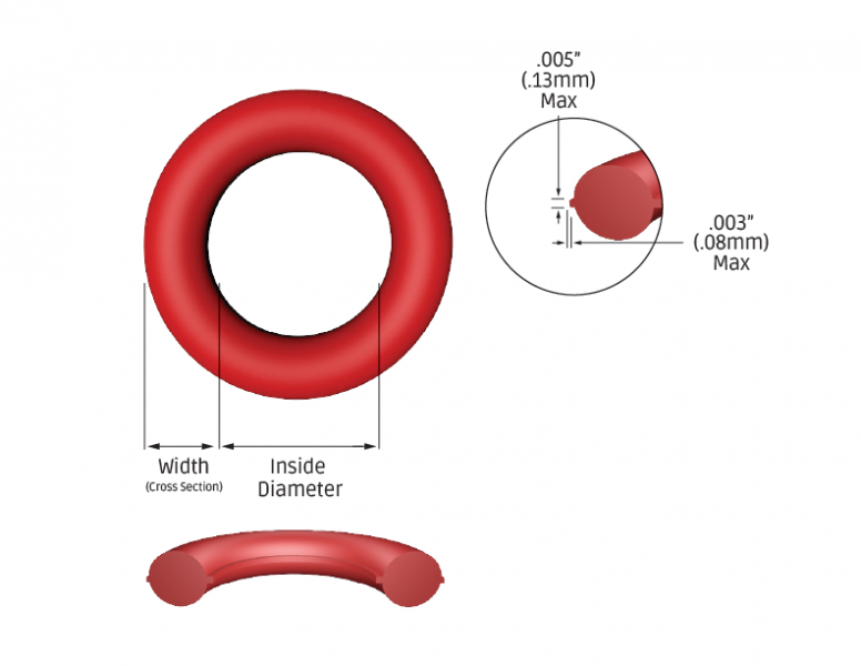
A MicrOring seal is generally defined as any o-ring with a measurement of less than 0.040 inches (1.00 mm) in either inside diameter or cross-section. Standard tolerances for a MicrOring’s inside diameter are ±0.004 inches (0.10 mm), and for its cross-section diameter, ±0.003 inches (0.08 mm).
Micro applications demand meticulous consideration of component tolerances and the impact of tolerance stacking on the o-ring seal. It’s crucial to recognize that the primary function of a seal is to accommodate the variation of mating hardware components. Consequently, calculating the minimum, nominal, and maximum tolerance conditions to determine the resulting squeeze and stretch of the MicrOring becomes paramount. Generally, for “normal” sized o-rings, a recommended stretch of up to 5% and a squeeze range of 10% to 40% for static applications and no more than 30% for dynamic applications are advisable.
Common configurations for o-ring seal applications include Axial Face, Radial Piston, and Radial Rod, which are also applicable to MicrOring seals. While the axial face configuration typically involves two components, the radial rod and piston configurations entail three components to consider when calculating tolerance stack.
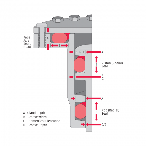
Example: Radial Piston Application
(Components are concentric)
MicrOring: .039 x .032
ID = .039 ±.004 (.043 / .035)
CS = .032 ±.003 (.035 / .029)
Bore Ø: .091 +.001/-.000 (.092 / .090)
Groove Ø: .041 +.000/-.001 (.041 / .040)
Calculate Minimum Squeeze:
=(Min o-ring CS — Max Gland Height)
=Min O-CS – ((Max Bore – Min Groove) / 2 )
= .029 – ((.092 – .040) / 2 ) = .029 – .026 = .003” (10.3%)
In the provided example, calculating the maximum squeeze conditions by adjusting the min and max values in the equation reveals that the maximum squeeze for this application is below 30%. Hence, the design using these dimensions and tolerances should perform well for both static and dynamic applications, with a maximum squeeze of up to 40% being permissible in static seal applications.
It’s important to note that the MicrOring ID may need to stretch over the piston during installation, especially when the inside diameter is less than the cross-section diameter. This relationship should also be considered for normal-sized o-rings. Depending on the elastomer material and hardness, the piston diameter should not exceed 2.5 times the o-ring ID.
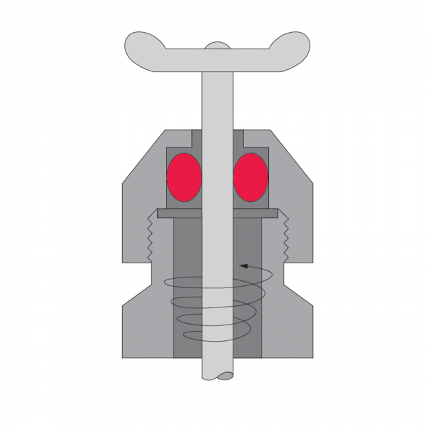
Designers may be tempted to apply a MicrOring in a piston configuration to an application requiring a rotating or reciprocating stem to be sealed. However, the required groove for the o-ring might make a section of the stem too thin. In such cases, a radial rod configuration is preferred, allowing for the application of a larger MicrOring cross-section without the issue of installing the o-ring ID over the piston.
Sound design principles apply to MicrOrings as with standard o-rings. Design for assembly by incorporating lead-in chamfers and smoothing sharp edges to prevent seal damage. Ensure the gland width is designed to accommodate the MicrOring’s maximum volume without exceeding the gland’s minimum void.
In summary:
- Design using the largest possible MicrOring cross-section for a robust design.
- Apply tight yet realistic tolerances to mating components, with special attention to MicrOring cross-section squeeze and inside diameter stretch.
- MicrOring cross-sections less than 0.020 inches (0.50 mm) are not recommended for radial configurations.
- Due to the unique nature of each MicrOring application, full testing to meet the application’s requirements is recommended.