Many different seal profiles are available. Some of the most common are round, square, and X-shaped. These are shown in static axial grooves below. The oring is an AS568-010 and groove dimensions are based on Aerospace Recommended Practice (ARP) 1234; Gland Design, Elastomeric O-Ring Seals, Static Axial.
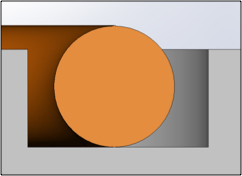
Round (oring)
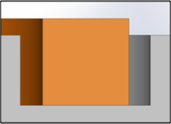
Rectangular (flat gasket)
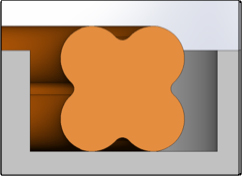
X-ring
Each gasket profile has advantages and disadvantages:
Round cross section gaskets and seals are in very common usage. The most common is the oring. The round profile of this seal creates a higher point load (stress) with a lower compressive force. The higher point load is advantageous because it creates a better seal between the bulk elastomer and the mating surface. The lower compressive force needed to compress the seal can minimize deflection of mating housings. One disadvantage of the round cross section is that gaskets and seals must be either molded or extruded. Die cutting and laser cutting are not possible.
Rectangular profile gaskets have the ability to bridge large surface imperfections because their entire width is in contact with the mating surface. The rectangular cross section lends itself to die and laser cutting; making prototyping simple, quick, and easy. A disadvantage of the rectangular profile is that significantly more force is needed to compress it.
X-Ring gaskets are popular in reciprocating applications where they can reduce friction. The disadvantage of this profile is its higher cost. These parts must be molded. Generally the molds are more intricate and expensive so the up-front costs are higher. The piece cost is also generally more because the molding process is more involved.
When each profile is compressed it contacts the mating surfaces differently. The width of the contact between the seal and the mating surface can vary greatly, as can the forces needed to compress the seals. The width of the contact area can be critical if the seal needs to bridge surface imperfections such as machine marks, scratches, porosity, or sinks on the mating surfaces. The contact area must be wider than the imperfection to form a seal.
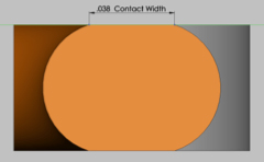
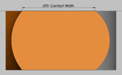
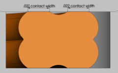
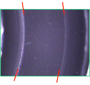
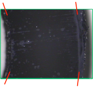
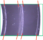
Below are profiles of the three cross sections discussed. The round cross section seal contacts 0.038” of the mating surface, the square cross section contacts 0.070”, and the X cross section contacts 0.022” twice, one for each lobe. Also shown below are views of the contact width taken using a transparent top to the compression fixture. The edges of the contact are a highlighted in red.
A designer will generally choose the largest contact area possible, but must also consider the compressive force needed activate the seal. Oftentimes designs require functional seals to compress with minimum force. Excessive compressive forces can bow housings, break fasteners, and make assembly cumbersome. Experience and testing have shown that round cross sections generally offer the best compromise between contact area and compressive force.
Example:
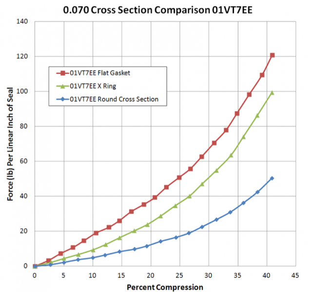
The round, square, and X profiles were molded based on the AS568-010 oring using a standard 75 durometer fluorocarbon, 01VT7EE. The molded parts were then compressed between parallel platens in a universal testing machine. Below is the plot showing force per linear inch of seal versus percent compression.
It is evident that the amount of force needed to compress the round cross section is significantly less than both the flat and X profiles. At lower amounts of compression the X profile acts more like an oring. The round lobes of the X profile initially compress similar to the round profile. As the compression increases, the round lobes become more flattended and the X profile acts more like a flat gasket.